by Charles Gonzales Gagui - CleVer Vibration
1. Reference
ASME A13.1-2007 [Revision of ASME A13.1-1996 (R2002)]
ANSI Z535.1-2006 (R2011) Reaffirmation of ANSI Z535.1-2006
2. Scope
This “Piping System Identification” is referenced to pertinent codes to create a consistent system that engineers will use in identifying substances inside piping systems for all industrial, commercial and institutional installations, and in buildings used for public assembly projects.
This standard includes Type and Size of Letters; Color scheme; and Location of identification markers. Identification can be done by stenciling, the use of tape, or markers.
This standard does not apply to buried pipelines or to electrical conduits.
3. Definition
Piping Systems - piping systems shall include piping of any kind including fittings, valves, and
pipe coverings. Supports, brackets, or other accessories are specifically
excluded from applications of this Standard. Piping is defined as conduits used
to convey, distribute, mix, separate, discharge, meter, control, or snub fluid
flows.
Flammable - this classification includes fluids, which under ambient or expected operating
conditions, are a vapor or produce vapors that can be ignited and continue to
burn in air. The term thus may apply, depending on service conditions, to fluids
defined for other purposes as flammable or combustible.
Combustible - this classification includes fluids that can burn, but are not flammable.
Toxic and Corrosive - this classification includes fluids that are corrosive or toxic, or will produce
corrosive or toxic substances when released.
Fire Quenching - this classification includes water, foam, and CO2used in sprinkler systems and
fire fighting piping systems.
4. Identification System
4.1 Legend
Legends are letters that must identify the name of the contents in full or abbreviated form with enough
information to identify the hazard such as temperature, pressure, etc.
4.2 Arrow
Arrows shall be used to indicate direction of flow. Where flow can be in both directions, arrows in both
directions shall be displayed.
4.3 Letter Style:
Times New Roman or Arial
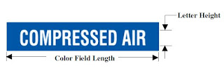
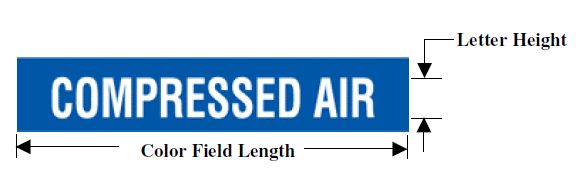
4.4 Letter Height Size and Color Field Length based on Pipe Size (Pipe size is the outside diameter of
pipe including insulation):

4.5 Color Designation

5. Location of Identification Markers

Pipe markers should be positioned so that they can be easily seen from the normal angle of approach for instance, below the centerline of the pipe if the pipe is overhead, and above the centerline if the pipe is below eye level. Labels are required at the following locations:
When the piping layout creates or occurs in a limited area of inaccessibility or of extreme complexity, such segments of layouts may require substitute techniques to achieve positive identification. Use of substitute techniques shall be limited to such segments and shall not deviate from the concept of identification described in this standard.
1. Reference
ASME A13.1-2007 [Revision of ASME A13.1-1996 (R2002)]
ANSI Z535.1-2006 (R2011) Reaffirmation of ANSI Z535.1-2006
2. Scope
This “Piping System Identification” is referenced to pertinent codes to create a consistent system that engineers will use in identifying substances inside piping systems for all industrial, commercial and institutional installations, and in buildings used for public assembly projects.
This standard includes Type and Size of Letters; Color scheme; and Location of identification markers. Identification can be done by stenciling, the use of tape, or markers.
This standard does not apply to buried pipelines or to electrical conduits.
3. Definition
Piping Systems - piping systems shall include piping of any kind including fittings, valves, and
pipe coverings. Supports, brackets, or other accessories are specifically
excluded from applications of this Standard. Piping is defined as conduits used
to convey, distribute, mix, separate, discharge, meter, control, or snub fluid
flows.
Flammable - this classification includes fluids, which under ambient or expected operating
conditions, are a vapor or produce vapors that can be ignited and continue to
burn in air. The term thus may apply, depending on service conditions, to fluids
defined for other purposes as flammable or combustible.
Combustible - this classification includes fluids that can burn, but are not flammable.
Toxic and Corrosive - this classification includes fluids that are corrosive or toxic, or will produce
corrosive or toxic substances when released.
Fire Quenching - this classification includes water, foam, and CO2used in sprinkler systems and
fire fighting piping systems.
4. Identification System
4.1 Legend
Legends are letters that must identify the name of the contents in full or abbreviated form with enough
information to identify the hazard such as temperature, pressure, etc.
4.2 Arrow
Arrows shall be used to indicate direction of flow. Where flow can be in both directions, arrows in both
directions shall be displayed.
4.3 Letter Style:
Times New Roman or Arial
4.4 Letter Height Size and Color Field Length based on Pipe Size (Pipe size is the outside diameter of
pipe including insulation):

4.5 Color Designation

5. Location of Identification Markers

Pipe markers should be positioned so that they can be easily seen from the normal angle of approach for instance, below the centerline of the pipe if the pipe is overhead, and above the centerline if the pipe is below eye level. Labels are required at the following locations:
- Adjacent to all valves and flanges
- Adjacent to all changes of direction
- On both sides of wall or floor penetrations
- At regular intervals on straight runs (50' is the acceptable maximum spacing, but closer spacing might be necessary for visibility.)
6. Unusual or Extreme Situations
When the piping layout creates or occurs in a limited area of inaccessibility or of extreme complexity, such segments of layouts may require substitute techniques to achieve positive identification. Use of substitute techniques shall be limited to such segments and shall not deviate from the concept of identification described in this standard.

No comments:
Post a Comment